In this example, readers will learn how to draw shear force & bending moment diagram of cantilever beam carrying udl(uniform distributed load) and point loads.
Example
Draw shear force and bending moment diagram of cantilever beam carrying UDL and point loads. As shown in figure below;
Solution
Shear Force
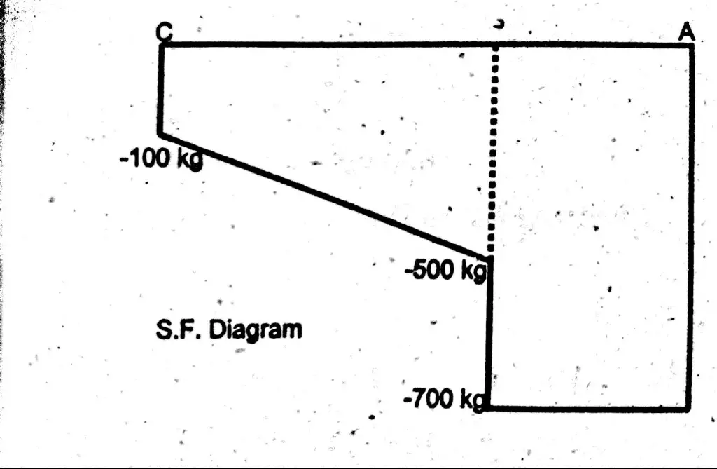
Let first draw shear force diagram. To draw shear force diagram, first find value of shear force at point C,B and A
Shear force will increase from left towards right. This is so, because shear force is always maximum on supports.
Shear force at point C = – 100 kg.
Shear force at point B = – 100 – (200 x 2) = – 500 kg.
Shear force at point B is the sum of point load and uniform load.
Shear force Between (B – A) = – 100 – (200 x 2) – 200
Shear force Between (B – A) = – 700 kg.
Shear Force Diagram
See the behavior, shear force become linear when udl comes into action.
Bending Moment
Similarly find values of bending moment at point C, B and A.
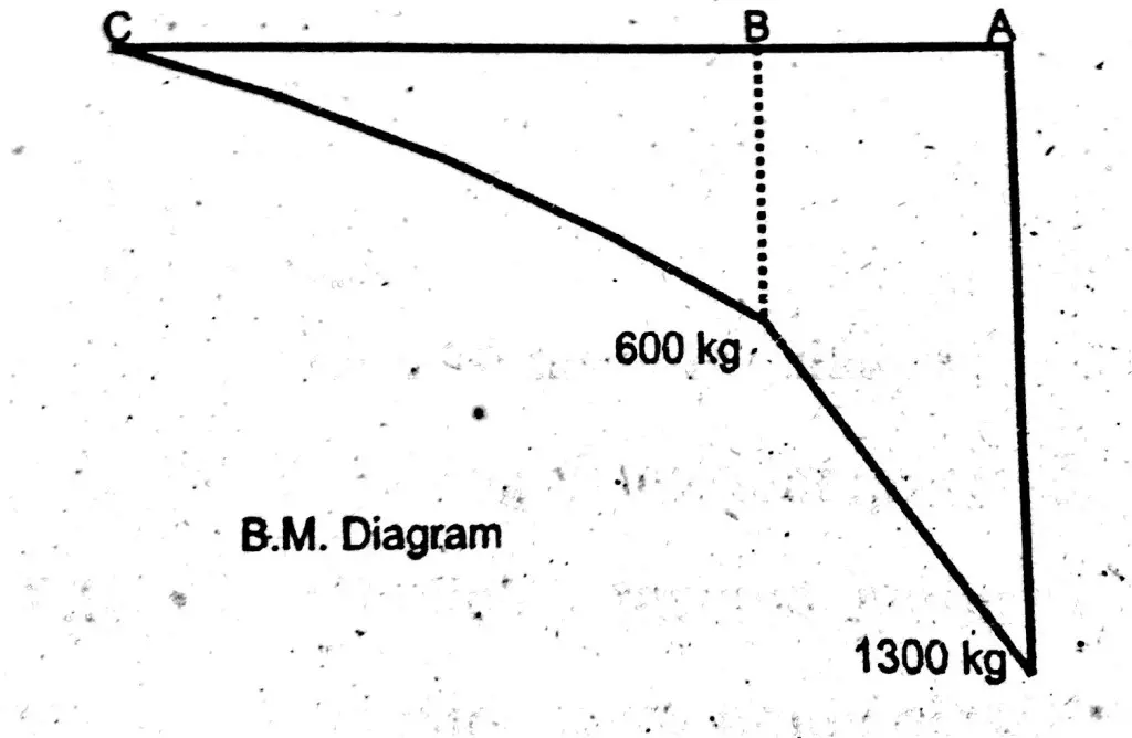
Bending Moment at Point C = B.M (C) = 0
To find bending moment because of uniform distributed load. Multiply the udl load with length covering upto that point and than multiply it with centroid of that lenght. As shown below;
Bending Moment at Point B = B.M (B) = – (100×2 + 200x2x1)
Bending Moment at Point B = B.M (B) = -600 kg.m
Bending Moment at Point A = B.M (A) = -[ 100×3 +200×2(1+1) + 200×1]
Bending Moment at Point A = B.M (A) = -1300 kg.m
Bending Moment Diagram
One can see that bending moment diagram is linear in area where only point load is coming. But, behavior of curve become first degree from where uniform distributed load is acting on it.


